


USER GUIDE
smart-MAIC D105
CONTENTS
-
Purpose of the device and its functions Controlled output
Temperature and/or humidity measurement Logic state measurement inputs.
-
Thank you for purchasing the relay smart-MAIC Е2. This device allows you to organize remote control of two loads, monitor temperature and humidity indicators. Connection to the Internet and data transfer is carried out via WiFi.
This section includes the following parts:
-
Device Purpose and Function
-
Controlled Output
-
Temperature and/or Humidity Measurement
-
Logic State Measurement Inputs
-
Device Component Locations
Purpose of the device and its functions
The device is designed to control two loads on command, on a schedule, or depending on the state of logic inputs or data coming from temperature and humidity sensors. The state of the inputs, temperature and humidity values are regularly transmitted to a cloud database.
The device measures the following parameters:
-
temperature using DS18x20 or DHT22 sensors
-
humidity using DHT22 sensors
-
state of logic inputs 1 or 0
Communication with the device is carried out using the IEEE 802.11 Wi-Fi wireless communication protocol.
The device transfers the accumulated data to a «cloud» server for further analysis and visualization. For more information about the processing capabilities of the data received from the device, see the WEB page www.smart-maic.com. Current data is available on the device’s built-in WEB site.
Controlled output
The device is equipped with two controlled outputs of the «dry contact» type. The controlled output is designed to automate load management.
The output is controlled remotely, on the device’s WEB page or from the server. It is also possible to control the output according to predefined rules and/or schedules.
Temperature and/or humidity measurement.
The device allows you to connect a maximum of 2 DS18x20 temperature sensors or one DHT22 temperature and humidity sensor.
Logic state measurement inputs.
The device has two inputs for measuring the logical state. The inputs are designed for connecting equipment that reports a change in state by closing its output contacts. The logical inputs have a state of «1». When the input is closed to GND, it assumes a state of «0». The logical state is measured at two inputs independently of each other.
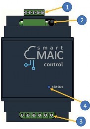
The device is made in a plastic case designed for installation on a DIN rail.
The figure shows the main components of the device.
1
Upper contact group
2
Reset button
3
Bottom contact group
4
Device status indicator
The device status indicator is located on the front panel. The indicator signals the following device states:
Indicator status
Device status
The indicator flashes quickly
searching and connecting to a wireless network
The indicator flashes slowly
possible to connect to the device as a wireless access point for initial configuration
The indicator is constantly on
connected to a wireless network
The indicator does not work
the device is turned off or faulty
-
-
-
WEB INTERFACE OF THE DEVICE
The WEB interface of the device is designed to view current data and configure device operation parameters. In the "Data" section, you can change the state of the controlled output.
Access to the device's built-in WEB site is via IP address and password. The time of inactivity on the device's website is limited to 5 minutes, after which you must re-enter the password to continue working with the device.
-
This section provides step-by-step instructions for installing, connecting, and configuring the device. Improper connection may result in damage to the device.
The section includes the following items:
-
Installation and connection to the power grid
-
Connection to a wireless network
-
Configuration of parameters
The device can be installed in an electrical panel on a DIN rail. To connect the device, follow these steps:
-
Connect the two wires of the logic output of the device. One wire to terminal N1 (GND) the second wire to the corresponding input, terminal N2 or N3.
-
Connect the temperature sensors. Black wire to terminal N1 (GND). Red wire to terminal N5 (+5V). Yellow wire (data) to terminal N4.
-
Connect the 220V power wires to the device to terminals N8 and N9. (N and L do not matter)
or from a 5V DC power supply to the upper terminals (1) and (5).
Upper contact group
1
GND (-5V)
2
logic input 1
3
logic input 2
4
temperature sensor input
5
+5 V
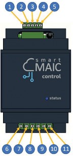
Lower contact group
6-7
controlled output 1
8-9
power supply 220 V
10-11
controlled output 2
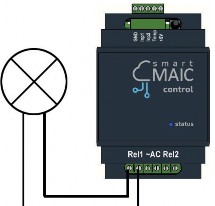
Typical diagram of connecting the load to the controlled output
CONNECTING TO A WIRELESS NETWORK
For more information see the Knowledge Base >>
For the device to work properly, it is necessary to ensure a stable signal of your wireless network at the installation location.
When you first start it up or after restoring factory settings, the device switches to wireless access point mode.
To connect to a wireless network, follow these steps:
-
On your computer or phone, go to the list of wireless networks and select the “smart-MAIC”+ (device number) network connection. If the “smart-MAIC”+(your device number) network is missing, press the Reset button on your device. The default connection password is none.
-
After successful connection, enter http://192.168.4.1 in the browser address bar and go to the device’s built-in WEB site.
-
In the “WiFi & Network” section, select your network name from the list of wireless networks, enter your network password, and click the “Connect” button. If your network name (SSID) is not in the list of wireless networks, refresh the list by clicking the “Refresh” button.
-
Refresh the connection status or reload the page and make sure the connection is successful and the status bar shows the internal IP address of the device. If the connection fails, repeat step 3.
-
Go to the device’s built-in WEB site using the IP address obtained during connection and continue configuring the parameters.
To complete the installation and connection of the device, configure the settings by following these steps:
-
In the «Configuration» section, select the WEB interface language that is convenient for you.
-
Change the password for logging into the device’s WEB interface. The password 0000 will not allow you to connect devices to your cloud server account. The password must consist of numbers and be no longer than ten. Your new password will allow you to access data from your device stored on the cloud server.
-
In the «Data» section, you can set the initial values of cumulative counters.
-
In the «Data Server» section, check the device’s connection to the cloud server.
-
In the «Status» section, view and copy the device ID for yourself. The device ID will be needed to connect the device to the «cloud server».

WARNING:
Remember the new password to log in to the device’s WEB interface. There is no password recovery mechanism. If you forget your password, perform a factory reset to regain access to the device and data.
CONFIGURATION OF INPUTS AND SENSORS:
-
In the Counter section, select the type of connected temperature sensors DS18x20 or DHT2. After saving the temperature sensor parameters, the device will re-search for connected sensors.
-
If necessary, match the connected sensors with the data sequence number (1-2).
Now your device is connected and ready to go.
-
-
DATA VALIDATION and RELAY CONFIGURATIN
Go to the device page in the «Data» section and check the correctness of the readings being taken.
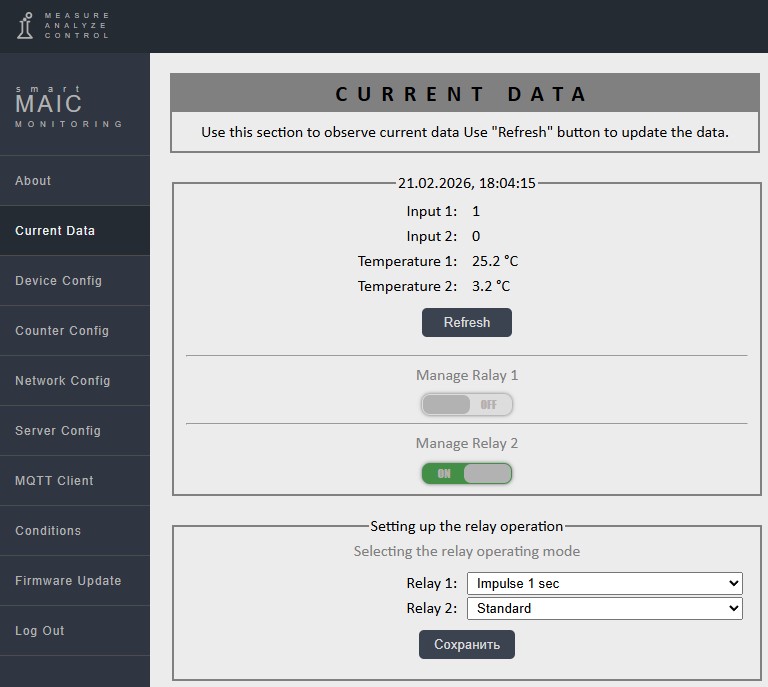
In the relay configuration section, select the relay operating mode: Standard or Impulse.
Standard mode is the normal operating mode of the relay, On or Off on command or condition.
In Impulse mode, the relay is always OFF. Upon command or condition, the relay will switch to the ON state for 1 second and then return to the OFF state.
The Impulse mode will be useful for controlling gates, roller shutters, blinds, and other devices that are controlled by pulses.
-
For more information see the Knowledge Base >>
The device supports data transfer and control of the «dry contact» output using the MQTT (Message Queue Telemetry Transport) service.
You can activate the MQTT service on the device’s WEB interface in the «MQTT Server» section.
To connect to the server, you must fill in the «Server Address», «Port» and «Username» fields.
The device periodically publishes data in the format <device number>.<topic name> to the following topics:
Topic name
Data
Description
T1-T2
°С
Sensor temperature
T2
% humidity
When DHT22 sensor is connected
In 1 - In 2
0 - 1
Status of logic inputs
OUT 1 - OUT 2
0 - 1
Status of relay outputs
JSON
Format JSON
All data in JSON format
To control the «dry contact» output, you must activate this feature on the device’s WEB interface in the «MQTT Server» section. Changing the output state is done by publishing the control command to the <device number>.SETOUTn topic. «n» is the output number 1 or 2.
The output enable command is «1». The output disable command is «0».
The «dry contact» output can be switched on no more than once every 20 seconds.
-
To restore factory settings, you must use the Reset button. The Reset button is located near the top group of contacts. The Reset button has two functions:
-
Reboot the device – press the Reset button. After pressing the Reset button, the device will reboot and enter wireless access point mode.
-
Restore factory settings – press and hold the Reset button for more than 5 seconds. After restoring factory settings, the device will reboot and enter wireless access point mode.
-
Connect to a wireless network and configure the device according to Chapter 3, “Connecting to a Wireless Network” and “Configuring Settings.”
The wireless access point mode is automatically turned off after
you finish working with the device’s WEB interface.
-
-
The device does not require periodic maintenance.
The device uses a CR 2032 3V lithium battery. The battery life is significantly affected by the temperature conditions of the device. If the battery fails completely, you will receive a notification from the «cloud» server about the need to replace the battery. The device will continue to operate with limited functionality.
The battery is replaced in the following sequence:
-
Disconnect the device from the power supply.
-
Unscrew the 4 screws connecting the device housing and remove
the upper part of the housing.
-
Remove the old battery from the holder.
-
Observe the polarity, insert the new battery into the holder.
-
Put on the upper part of the housing and tighten the 4 screws.
-
-
For more information see the Knowledge Base >>
The function of checking data for compliance with specified conditions allows you to automate the operation of a controlled output or receive notifications.
It is possible to set several conditions. Conditions are processed sequentially, top to bottom, the relay will take the state of the last executed condition. If the value of the selected data type corresponds to the specified value and condition, the device will perform one of the selected actions: sending an email; turning on the relay; turning off the relay. Conditions are checked with an interval of 5 seconds.
To eliminate false positives, you can enable a delay in seconds «Filter to [sec]» during which the condition will not be executed.
Condition checking can be limited by time. If you activate the time interval, the condition action will be executed only within the specified time.
Condition settings are available on the device’s WEB interface in the «Conditions» section.
To activate a condition, you must select the data type, select the comparison sign «>» or «<», enter the value for comparison, and select the required action.
Example: If you need to turn on the relay when the temperature drops below 10 °C and turn off the relay when the temperature reaches 24 °C, you need to enable two conditions:
-
T1 < 10 Relay ON
-
T2 > 12 Relay OFF
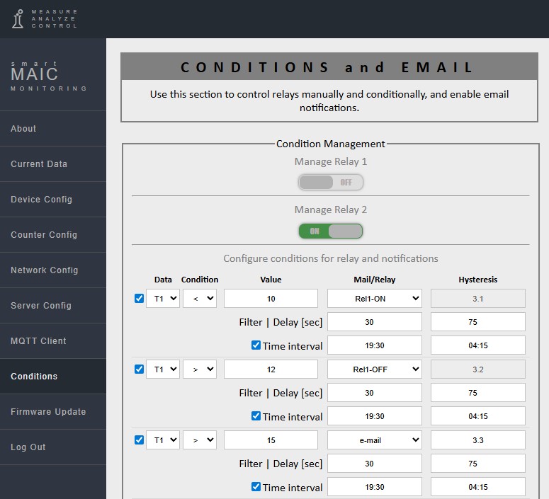
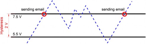
Hysteresis is set only for the action - sending an e-mail.
Hysteresis is designed to prevent sending repeated e-mail messages when the value of the selected data continues to meet the specified condition.
Important! To avoid spam, set a sufficiently large hysteresis value.
Example of hysteresis operation for the condition:
T > 7.5 - e-mail, hysteresis: 2.0
The event notification feature allows you to activate email notifications about selected events that occur with the device.
-
-
Main characteristics of the device and ranges of measured values
Logic input
two, closing contacts
Temperature measurement DS18x20
–55°C +125°C, accuracy ±0.5°C
DHT22 temperature and humidity
measurement
–40°C +80°C,
humidity 0-99%
Temperature sensors
max. 2 or DHT22 – 1
Maximum load power on the controlled output
3000W at 230V, 14А
Self-consumption
< 1.0W
Wireless communication protocol
2.4 GHz / IEEE 802.11 (b, g, n)
Data update interval
5 sec.
Data collection interval
60 sec.
Maximum data accumulation time in the absence of communication with the server
50 days
Set operating temperature range
from -40°C to +70°C
AC or DC power supply
100–240 V, 50-60 Hz; 5V; 0,6A DC
Dimensions LxHxW
90х67х52 mm.
Mounting type
on DIN rail
Weight
0,1 kg
The data obtained during the measurements are sent to the database on the «cloud server». Access to data is carried out using the smart-MAIC Dashboard service.
For data visualization and analysis it is necessary:
-
Create your account on the «cloud server», for this, follow the link dash.smart-maic.com >>
Follow the steps necessary for registration.
-
In the «Devices» menu, select «Add Device» and enter the following data:
-
Device name - an arbitrary name for your device
-
Device ID - the ID of your device can be viewed on the device WEB interface in the “Status” tab
-
Password - the password that you set on your device.
-
After connecting a new device, you will be asked to automatically create two pre-configured boards for displaying data on a PC and mobile device.
For more information about the Dashboard, see the Knowledge Base >>

-
-